


Introduction to Networking
The FLUIDLINK® i400 Intelligent Laboratory Pump is equipped with a wide range of built-in automation connectivity. This User Manual will guide you through the proper configuration and operation of the i400's INDUSTRIAL and REMOTE networking, including how to apply any needed updates to the onboard network drivers.
Who should read this Manual?
Intended Audience
Sections relating to LAN SETTINGS and FLUIDLINK.IO (the FLUIDLINK Cloud) are written for Novice Users and only require a basic understanding of internet (TCP/IP) addressing. The remainder of the networking section of the User Manual is written for use by more Advanced Users, specifically Automation Engineers.
The sections which cover industrial networking require an advanced engineering skillset which includes network wiring and configuration of the PLC/DCS client control system. The scope of this manual does not include configuration details or specifics of any client PLC/DCS control system.
WHAT TO DO NEXT:
- Scroll to FLUIDLINK.IO for connecting to the FLUIDLINK Cloud.
- Scroll to MODBUS RTU for connecting to a MODBUS RTU network.
- Scroll to MODBUS TCP/IP for connecting to a MODBUS TCP/IP network.
- Feel free to ask for assistance:
FLUIDLINK.IO
OVERVIEW OF STEPS FOR LINKING PUMP TO FLUIDLINK.IO SERVICES:
- Connect the MAINTENANCE RJ45 (see BACK PANEL) to an internet connection.
- On the i400, go to SETTINGS > NETWORK SETTINGS > FLUIDLINK.IO.
- Ensure that Cloud indicator reads "AVAILABLE".
- Press LINK ACCOUNT button, changing the CURRENT LINK STATUS to "PENDING_LINK".
- Make a note of the 4-digit PIN# displayed.
- From a browser go to https://connect.fluidlink.io/ and follow the on-screen instructions.
LINKING your pump to the FLUIDLINK.IO Cloud:
CONNECT PUMP TO THE INTERNET
Connect the MAINTENANCE RJ45 (on the BACK PANEL) to an internet connection. The pump will attempt to acquire an IP Address via DHCP, and then attempt to reach the FLUIDLINK.IO Service. With a successful connection the FLUIDLINK.IO Cloud Service Indicator will update to "AVAILABLE".
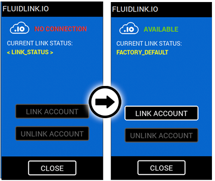
Figure 14.2: Connect pump to the Internet.
If after 60 seconds you continue to see "NO CONNECTION", please verify the RJ45 is connected to the correct port on the pump, and check the LAN SETTINGS.
INITIATE "LINK ACCOUNT" & GENERATE PIN#
The LINKING process uses a one-of-a-kind combination of your pumps Serial Number and a uniquely generated PIN#, which expires after a single use. If ever you elect to remove your pumps connection to the cloud (UNLINK the pump) you can do this by simply pressing the UNLINK ACCOUNT button on this screen. If you press the LINK ACCOUNT button again in the future an entirely different PIN# will be generated. This PIN# process ensures privacy and allows for transferring custody of the pump without concern that someone has retained your PIN#.
From the SYSTEM SETTINGS menu (A), select NETWORKING (B), select FLUIDLINK.IO (C), and press the LINK ACCOUNT button (D). The CURRENT LINK STATUS should change to "PENDING_LINK ( PIN# _ _ _ _ )" (make a note of the unique 4-digit PIN# displayed), indicating that your pump is ready for the next step in the linking process.
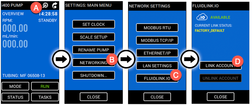
Figure 14.3: Initiating LINK ACCOUNT to generate PIN#.
COMPLETE CONNECTION BY SELECTING "LINK (+ADD) A PUMP..."
From a browser go to https://connect.fluidlink.io/ and follow the on-screen instructions to complete the linking process, and begin operating your i400 Pump from anywhere!
SECURITY NOTE: THE FLUIDLINK.IO TRANSPORT LAYER SECURITY ("TLS") WILL REPORT AN ERROR IF THE SYSTEM CLOCK ON THE PUMP ISN'T ACCURATELY SET.
IMPORTANT: IF YOU MAKE CHANGES TO THE SYSTEM CLOCK BE CERTAIN TO RESTART (REBOOT) THE PUMP PRIOR TO LINKING TO THE FLUIDLINK.IO SERVICE. FAILING TO RESTART THE PUMP AFTER CHANGING TIME-ZONE SETTINGS WILL CAUSE PUMP READINGS TO BE TIMESTAMPED INCORRECTLY.
MODBUS RTU
This section of the manual is pending, please view the list of MODBUS Registers and contact our support department for assistance. This section of the manual is scheduled to be updated very soon - please CONTACT SUPPORT if you need immediate assistance configuring your device.
MODBUS TCP/IP
This section of the manual is pending, please view the list of MODBUS Registers and contact our support department for assistance. This section of the manual is scheduled to be updated very soon - please CONTACT SUPPORT if you need immediate assistance configuring your device.
RANGE: 40001-40015
i400 MODBUS RTU & MODBUS TCP/IP Register Mapping
| Start REG | # REGs | Format | Parameter | UoM | Fn. Codes | Min. - Max. | Res. | Default |
|---|---|---|---|---|---|---|---|---|
| 40001 | 1 | UINT_16 | RUN/STOP (PV) | n/a | 03 | 0 - 1 | 0 | n/a |
| Running Status of Pump Motor: "0" (stopped), "1" (running). | ||||||||
| 40002 | 1 | UINT_16 | RUN/STOP (SP) | n/a | 03, 06 | 0 - 1, 98 - 99 | 0 | n/a |
| Set to "0" to stop, "1" to start Pump Motor. Note: This register will be set to "98" or "99" if operator uses GUI to Start/Stop system, or "96" or "97" if EMF or DOSING process Starts/Stops the pump running. | ||||||||
| 40003 | 2 | FLOAT | SPEED (PV) | RPM | 03 | 0.01 - 400.00 | 0.00 | n/a |
| Current Pump Motor speed (RPM) setting, independant of the current Running Status. Will not alter current RUN/STOP state. | ||||||||
| 40005 | 2 | FLOAT | SPEED (SP) | RPM | 03, 06, 10 | 0.01 - 400.00 | 0.00 | n/a |
| Pump Motor speed (RPM) setpoint. Speeds set above or below Min/Max range will be ignored. | ||||||||
| 40007 | 2 | FLOAT | FLOW RATE (PV) | mL/min | 03 | 0.00 - NNN.NN* | 0.00 | n/a |
| FLOW RATE is a shared reading for both MANUAL and EMF modes of operation. | ||||||||
| 40009 | 2 | FLOAT | FLOW RATE EMF (SP) | mL/min | 03, 06, 10 | 0.NN - NNN.NN* | 0.00 | n/a |
| Updates the FLOW RATE of an active (running) Exponential Mass Flow (EMF) process. | ||||||||
| 40011 | 2 | FLOAT | FLOW RATE CALCULATED (SP) | mL/min | 03, 06, 10 | 0.NN - NNN.NN* | 0.00 | n/a |
| Updates the FLOW RATE when operated in MANUAL delivery mode. | ||||||||
| 40013 | 2 | FLOAT | TOTALIZER CALCULATED (PV) | mL | 03 | 0.0 - N.N | 0.0 | n/a |
| Calculated volume delivered (calculations internal to i400) since last RESET/ZERO of Totalizer. | ||||||||
| 40015 | 2 | FLOAT | TOTALIZER SCALE (PV) | mL | 03 | 0.0 - N.N | 0.0 | n/a |
| Volume delivered as reported by scale (balance) feedback since last RESET/ZERO of Totalizer. | ||||||||
APPENDIX
FOR PLACEMENT ONLY:
( This page left intentionally blank )
WHAT TO DO NEXT:
- Return to the beginning of the USER MANUAL.